PROJECT 1
1. Preparation
In a project students prepare their own set ups and enjoy greater freedom to do things making their own decisions. Here we discuss about a project that generates experience about how digital electronic circuits are implemented in the fundamental level.
Every student studying science and engineering must have a breadboard and some accessories like resistors, transistors, diodes, capacitors, a power supply/battery and some multimeter(LEDs for makeshift). For the current project we request the students to get prepared with them. A detailed list is given below.
Breadboard
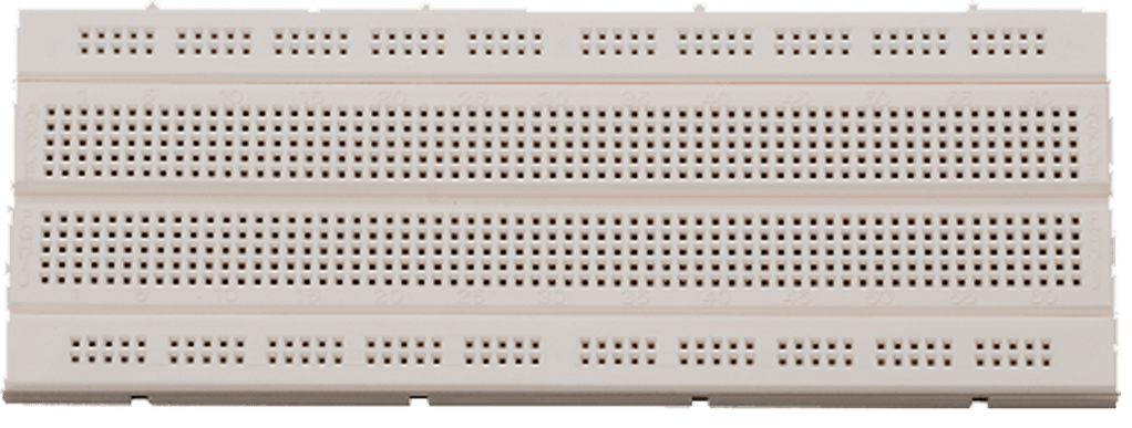
We recommend to buy or collect a spare students’ breadboard (Aluminium). It costs between ₹ 120 and ₹ 200. Its connected holes are as shown below:

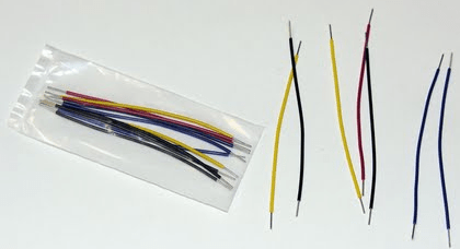
Connecting wires
Power supply

It is possible to drive circuits with 9v batteries as shown in the figure, but buying a power supply is cheaper in long run. Buying from a retail store is recommended. One can also search online like
Resistors
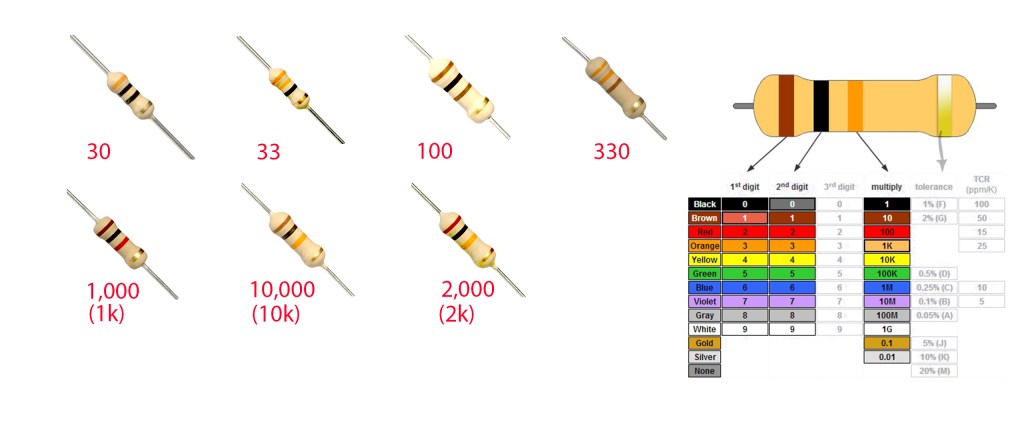
In the figure carbon filament resistors (CFR) are shown. We recommend to buy some 100, 330, 1k, 3.3k and 10k ohms of resistors 1 dozen of each kind. They will cost ₹ 20 to ₹25 (6 dozens). Please see above how to read their values.
Capacitors
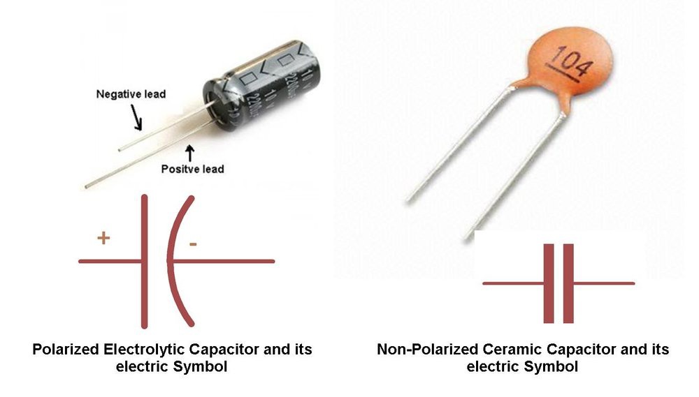
some 1 μF, 10μF, 100μF of electrolytic capacitors of 25V and 0.1μF, 0.01μF and 0.001μF of ceramic capacitors are recommended to buy. They may cost ₹ 30 around.
Transistors
Buy one dozen of BC548 or BC547 transistor(NPN audio frequency type). Total cost is around ₹60.
LEDs
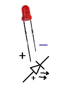
Buy a few red LEDs.
We recommend to buy all the articles from a retail shop of spare electronic parts. Alternatively one can explore some online options like:
We are going to publish here some demonstrations of circuit making and executing on a breadboard once you students are all prepared with the equipments this week. You can study very simple digital circuits and then design your own combination circuits in this project.
Discussion is possible here in the google form:

1. Demonstration
Clock here to View Circuit Diagram
Click for the format of the Working Manual
